How to Read a Cutting Diagram (And Follow It at the Saw)

How to Read a Cutting Diagram (And Follow It at the Saw)
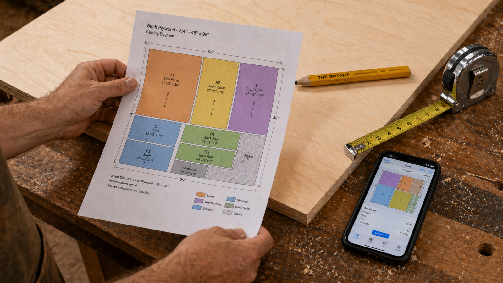
You've planned your project, built your cut list, and run it through an optimizer. Now you're holding a cutting diagram — a colour-coded map of rectangles, labels, and numbers printed on a sheet of paper or glowing on your phone screen. If you've never worked from one before, it can look a little confusing at first. What do the colours mean? Which number is the width and which is the length? Where do you make the first cut? This beginner-friendly guide walks you through exactly how to read a woodworking cutting diagram from top to bottom, and how to translate it into accurate, confident cuts at the table saw or track saw. If you're using the Cut Optimizer app, you'll also learn how to get the most out of its interactive layout viewer and step-by-step cutting guide.
📐 Generate Your Own Cutting Diagram in Seconds
Cut Optimizer turns your parts list into a clear, colour-coded cutting diagram with a step-by-step guide you can follow right at the saw. Supports iPhone and iPad with PDF and SVG export.
What Is a Cutting Diagram?
A cutting diagram (also called a cutting layout, cut sheet diagram, or board layout) is a scaled visual representation of how your parts are arranged on a stock sheet of material. It shows exactly where each piece sits on the plywood, MDF, or melamine panel, and communicates everything you need to know to reproduce that layout accurately at the saw.
Think of it as a treasure map for your material. Every rectangle on the diagram is a part you need to cut. The spaces between rectangles represent the saw kerf — material consumed by the blade. The overall rectangle that contains everything is your stock sheet. A good cutting diagram tells you not just what to cut, but where to cut it and in what order.
Cutting diagrams can be produced by hand on graph paper, generated by desktop software, or created instantly by a cut list optimizer app. Regardless of the source, the core elements are the same.
The Anatomy of a Cutting Diagram
Before you can follow a cutting diagram, you need to understand what each element means. Here are the key components you'll find on any woodworking cutting layout:
The Sheet Outline
The large outer rectangle represents your full stock panel — for example, a standard 2440 × 1220 mm (8 × 4 ft) sheet of plywood. This is the physical piece of material you start with. The diagram is scaled proportionally, so larger sheets look larger than smaller ones. If your project uses multiple sheets, you'll have a separate cutting diagram for each one.
Part Rectangles
Each smaller rectangle inside the sheet outline is an individual part to cut. In a colour-coded diagram from an app like Cut Optimizer, each part gets a distinct colour to help you distinguish it visually — particularly useful when several similarly sized parts are close together on the sheet.
Part Labels
Inside or beside each part rectangle, you'll typically find:
- Part name or code — e.g. "Left Side Panel" or "P1"
- Dimensions — width × length, usually in the format "400 × 720 mm" or "15¾" × 28⅜""
- Quantity indicator — if multiple identical parts appear on different sheets, a number shows which instance this is
Grain Direction Arrow
On diagrams for veneered plywood or faced sheet goods, a small arrow on each part rectangle indicates which direction the grain runs. An arrow pointing along the length of the part means grain runs lengthwise; an arrow pointing across the width means cross-grain orientation. Always check this before cutting any appearance-grade part.
Waste / Offcut Areas
Any area on the sheet that isn't occupied by a part rectangle is waste or usable offcut. Many cutting diagrams shade these areas in grey or leave them blank. Some optimizers, including the Cut Optimizer app, also display a waste percentage for each sheet — a useful at-a-glance indicator of how efficiently your parts are nested.
Cut Lines
The borders between adjacent parts represent cut lines — where the blade will pass. The gap between adjacent part rectangles on the diagram represents saw kerf: the material the blade removes. On well-drawn diagrams, this gap is visible even at small print sizes as a thin white space between parts.
💡 Beginner Tip: When reading dimensions on a cutting diagram, always check the units. Apps and software may display dimensions in millimetres, inches, or fractional inches. The Cut Optimizer app supports both metric and imperial — including fractional input like ¼", ⅛", and 1/16" — so your diagram will match whichever system you work in.
How to Orient the Diagram to Your Physical Sheet
Before making any marks or cuts, establish the correct orientation between your diagram and the physical sheet in front of you. This is a step many beginners skip — and it leads to parts cut with the grain running the wrong way, or a layout that doesn't match the sheet's actual dimensions.
Follow this sequence every time:
- Identify the top-left corner — most cutting diagrams are drawn with the sheet's long edge running horizontally. The top-left corner of the diagram corresponds to the top-left corner of your physical sheet as you face it.
- Check the grain direction — for plywood, the face grain typically runs along the long dimension of the sheet (left to right when the sheet is landscape-oriented). Confirm this matches the grain direction arrows on your diagram.
- Trim the factory edges first — before cutting any parts, trim a small amount (5–10 mm) from the left long edge and the bottom short edge to create two true reference edges. These become your 0,0 origin point — the corner from which all measurements on the diagram flow.
- Mark the sheet's orientation — use chalk or a lumber crayon to mark "TOP LEFT" on the appropriate corner of the physical sheet so you don't lose orientation when flipping or moving the panel.
How to Read Part Dimensions on the Diagram
Part dimensions on a cutting diagram are almost always expressed as width × length or width × height, where width is the shorter horizontal measurement and length is the longer vertical measurement as the part appears on the sheet. However, this convention isn't universal — some software labels dimensions as "X × Y" relative to the sheet axes.
The safest approach is to verify dimensions directly from the diagram by cross-referencing with your original cut list. If a part is labelled "400 × 720 mm" on the diagram and your cut list records it as "400 mm wide × 720 mm long," you're reading it correctly. If the numbers are reversed compared to your cut list, the optimizer has rotated the part — which is fine dimensionally, but you need to check whether the grain direction arrow still matches your requirement.
⚠️ Watch Out: If a part appears rotated on the diagram relative to your original cut list entry, always check the grain direction arrow on that part before cutting. A rotated part with a locked grain direction requirement is a red flag — it means the optimizer may have placed it incorrectly, or you may have entered the grain setting wrong. Verify before committing the cut.
Understanding the Step-by-Step Cutting Guide
A cutting diagram tells you where parts sit on the sheet. A step-by-step cutting guide tells you which order to make the cuts. These two elements work together — and following the cutting order matters more than most beginners realise.
The Cut Optimizer app generates both simultaneously. The cutting guide sequences cuts to follow the guillotine constraint — meaning every cut runs fully from one edge of the remaining panel to the other, the way a table saw or panel saw actually operates. This is critical because non-guillotine arrangements that look efficient on paper cannot actually be cut on a standard table saw without complex jigs and re-sequencing.
A typical step-by-step cutting guide entry looks like this:
| Step | Cut Type | Measurement | Result |
|---|---|---|---|
| 1 | Rip cut | 420 mm from left edge | Strip A (420 × 1220 mm) |
| 2 | Crosscut Strip A | 740 mm from bottom edge | Part: Left Side Panel (400 × 720 mm) |
| 3 | Crosscut Strip A | 740 mm from bottom edge | Part: Right Side Panel (400 × 720 mm) |
| 4 | Rip cut remainder | 630 mm from left edge | Strip B (630 × 1220 mm) |
Notice how the guide works in stages: first a rip cut divides the sheet into vertical strips, then crosscuts divide each strip into individual parts. This rip-first approach is the standard workflow for breaking down full sheets with a table saw and keeps pieces manageable throughout the process.
Rip Cuts vs. Crosscuts — What the Diagram Is Telling You
Every cut in a cutting diagram is either a rip cut or a crosscut, and understanding the difference helps you set up correctly at the saw:
- Rip cut — a cut that runs parallel to the grain (along the long dimension of the sheet). Made with the fence on a table saw, or with a guide rail set parallel to the long edge on a track saw. Rip cuts divide the sheet into strips.
- Crosscut — a cut that runs perpendicular to the grain (across the width of the sheet or strip). Made with a crosscut sled or mitre gauge on a table saw, or with the guide rail set perpendicular on a track saw. Crosscuts divide strips into individual parts.
The step-by-step guide from the Cut Optimizer app explicitly labels each cut as a rip or crosscut, so you always know which fence orientation or guide rail angle to use before picking up the piece.
How to Transfer Measurements from Diagram to Physical Sheet
Once you understand the diagram and cutting sequence, the physical transfer is straightforward. Here's the process step by step:
- Set your saw fence or guide rail to the measurement shown for the first cut in the cutting guide. Always measure from your reference edge (the trued factory edge), not from a previous cut.
- Double-check the measurement with a tape measure against the fence before cutting. The fence reading and the tape should agree.
- Make the cut and label the piece — immediately after each rip cut, write the strip label (e.g. "Strip A") on the piece with chalk so you don't confuse strips later.
- Cross-reference with the diagram after each cut. Tick or cross off each completed step in the cutting guide — on the printed PDF, or by working through the in-app guide on your Cut Optimizer screen.
- Mark each finished part with its part name once it's cut to final size. Use chalk on the face or low-tack tape on the edge so the mark is clearly legible but won't damage the surface.
💡 Pro Tip: Work through the cutting guide on your phone in the workshop by propping your iPad or iPhone on a stand beside the saw. The Cut Optimizer app highlights the active cut in the layout viewer as you work through the guide, so you can always see exactly which piece on the sheet you're cutting next — even with sawdust on your hands.
Reading Multi-Sheet Diagrams
Projects with many parts often span multiple sheets of plywood. A multi-sheet cutting diagram set gives you one layout per sheet, numbered sequentially — Sheet 1, Sheet 2, Sheet 3, and so on. Each sheet diagram is independent and shows only the parts assigned to that particular sheet.
When working from a multi-sheet set, keep the following in mind:
- Cut one sheet at a time, completing all cuts on Sheet 1 before moving to Sheet 2. Mixing sheets mid-session creates confusion and mislabelled parts.
- Check which sheet a part is assigned to before marking your material. Some parts that look identical (e.g. two shelf panels of the same size) may be split across different sheets — this is normal and intentional.
- Label each sheet of raw material with a chalk number before you start cutting ("Sheet 1," "Sheet 2") so you can't accidentally start cutting Sheet 2's layout on Sheet 1's material.
- Use the Cut Optimizer's PDF export to print a separate cutting diagram for each sheet, and work from the printed sheet in the workshop while keeping the phone available for the interactive step-by-step guide.
Common Mistakes When Following a Cutting Diagram
| Mistake | What Goes Wrong | How to Avoid It |
|---|---|---|
| Cutting in a different order to the guide | Strips become too small to safely handle on the table saw; parts can't be cut without re-sequencing | Always follow the cutting guide sequence, even if a different order seems logical to you |
| Measuring from the wrong edge | Every cut on the sheet shifts by the width of the untrimmed factory edge — parts come out wrong size | Always measure from your two trued reference edges, not raw factory edges |
| Ignoring grain direction arrows | Visible parts end up with cross-grain orientation — looks wrong in the finished piece | Check grain arrow on every appearance-grade part before cutting |
| Not labelling parts immediately after cutting | Similar-sized parts get mixed up; wrong pieces get machined or assembled | Write the part name on every piece the moment it's cut free from the sheet |
| Flipping the sheet without updating orientation | The diagram's left becomes the sheet's right; all measurements are mirrored | Mark the reference corner of the sheet with chalk before any cuts and never flip without re-checking |
How the Cut Optimizer App Makes This Easier
Reading and following a hand-drawn or printed cutting diagram requires constant cross-referencing between the diagram, the cutting guide, and the physical sheet. The Cut Optimizer app for iPhone and iPad integrates all three into one interactive experience:
- Interactive layout viewer — pinch to zoom and pan on the cutting diagram. Tap any part rectangle to see its name, dimensions, grain direction, and edge banding requirements.
- Active cut highlighting — as you work through the step-by-step guide, the current cut is highlighted on the layout viewer in real time, so you can always see exactly where you are on the sheet.
- Fullscreen mode — expand the diagram to fill the screen for easier reading at the saw, even with safety glasses on and sawdust in the air.
- PDF and SVG export — generate a printable cutting diagram to hang on the workshop wall or bring to a panel saw, so you don't need the phone at the saw if you prefer paper.
- iCloud sync — start a project on your iPhone at the lumber yard and pick it up on your iPad in the workshop without any manual file transfer.
✅ Verdict: A cutting diagram is only as useful as your ability to read and follow it accurately. For beginners especially, the interactive step-by-step guide in a dedicated app like Cut Optimizer removes the biggest sources of confusion — cutting order, part orientation, and measurement transfer — and replaces them with a clear, sequential workflow you can follow with confidence from the first rip cut to the last crosscut.
📱 Get Your Cutting Diagram Ready Before You Go to the Saw
Cut Optimizer generates colour-coded cutting diagrams, waste statistics, and an interactive step-by-step guide for your iPhone or iPad. Export as PDF to print for the workshop, or work directly from the app's fullscreen layout viewer. Free to download.
Frequently Asked Questions
What does a cutting diagram show?
A cutting diagram is a scaled visual layout that shows how all your parts are arranged on a stock sheet of material. It displays each part as a labelled rectangle with its dimensions and grain direction, and the overall sheet outline as the outer boundary. Combined with a step-by-step cutting guide, it tells you exactly where every cut goes and in what order to make them. Apps like Cut Optimizer generate cutting diagrams automatically from your parts list.
How do I know which direction to orient the cutting diagram on my sheet?
Most cutting diagrams are drawn with the sheet in landscape orientation — long edge running left to right. The top-left corner of the diagram corresponds to the top-left corner of your physical sheet as you face it. Before cutting anything, identify your two true reference edges (after trimming the factory edges) and align them with the diagram's left and bottom edges. Mark the reference corner with chalk to maintain orientation throughout the cutting session.
What is the difference between a rip cut and a crosscut on a cutting diagram?
A rip cut runs parallel to the grain — along the long dimension of the sheet — and is typically the first type of cut made when breaking down a full panel into strips. A crosscut runs perpendicular to the grain, dividing strips into individual parts. A step-by-step cutting guide from a cut list optimizer app labels every cut as a rip or crosscut so you know which saw setup to use for each step.
Why does my cutting diagram show parts in different colours?
Colour coding is used to help you visually distinguish between different parts — especially helpful when several similarly sized pieces are placed close together on the same sheet. Each colour corresponds to a specific part or part type in your cut list. Some optimizers use colour to differentiate between materials or thicknesses. The colour itself has no impact on how you cut; it's purely a visual reference aid.
Do I have to follow the cutting order in the step-by-step guide, or can I cut in any order?
You should always follow the cutting sequence in the guide. The order is not arbitrary — it's calculated to ensure every cut is a full edge-to-edge guillotine cut that can be made on a standard table saw or track saw without unsafe off-cuts or impractical piece handling. Deviating from the sequence often results in strips that are too narrow to pass safely through the table saw, or an arrangement that can't be completed with standard equipment.
Can I use a cutting diagram from a phone app in the workshop without printing it?
Yes — this is one of the main advantages of using a mobile app like Cut Optimizer. The app's fullscreen layout viewer and interactive step-by-step guide are designed for workshop use, with large text and touch navigation that works even with gloves or a dusty screen. If you prefer paper, the PDF export produces a print-ready cutting diagram at the correct scale. Many woodworkers use both — the printed diagram on the wall for reference and the app on a stand for the interactive cut-by-cut guide.
how to read a cutting diagram woodworkingwoodworking cutting layout explainedrip cut vs crosscut plywoodcutting diagram for beginnershow to follow a cut list diagramcut list optimizer cutting guideplywood sheet layout diagramstep by step cutting plan woodworking