How to Account for Saw Kerf in Your Cut List

How to Account for Saw Kerf in Your Cut List
Saw kerf is one of the most technically misunderstood concepts in woodworking cut planning — and one of the most expensive to get wrong. It's invisible at the planning stage, easy to dismiss as negligible, and capable of derailing an entire sheet's worth of parts when ignored. Whether you're building a single cabinet box or a full kitchen installation across a dozen sheets of plywood, understanding how to account for kerf in your cut list is the difference between parts that fit perfectly and parts that come up short. This guide explains exactly what kerf is, how it accumulates across a layout, how to calculate it manually, and why a dedicated cut list optimizer handles all of it automatically so you don't have to.
⚙️ Let the Optimizer Handle Your Kerf Automatically
Cut Optimizer accounts for saw kerf on every cut in your layout. Enter your blade thickness once and every spacing, sheet count, and waste calculation adjusts automatically — no manual arithmetic required.
What Is Saw Kerf?
Saw kerf is the width of material removed by a saw blade during a single cut. As the blade's carbide teeth pass through the wood, they don't just separate two pieces — they pulverise a thin channel of material into sawdust. That channel has a measurable width: typically 2.4–3.2 mm for table saw blades, around 2.5–3 mm for track saws, and up to 6.35 mm for a quarter-inch CNC router bit.
On any single cut, the kerf loss is so small it seems irrelevant. But cut planning is a cumulative exercise. A sheet with 15 rip cuts and 10 crosscuts loses 25 kerf-widths of material before a single finished part reaches the assembly bench. At 3 mm per cut, that's 75 mm — nearly 3 inches — of material consumed by the blade alone, with no finished parts to show for it.
This is why kerf is built into every professional cut planning method, and why the Cut Optimizer app includes a dedicated kerf field as a core setting, not an optional extra.
Why Ignoring Kerf Causes Real Problems
Consider a simple example: you need to rip three 380 mm wide panels from a 1220 mm wide sheet. Without kerf:
3 × 380 mm = 1140 mm — fits on 1220 mm with 80 mm to spare ✓
Now apply a realistic 3 mm kerf for the two cuts between the three panels:
(3 × 380 mm) + (2 × 3 mm kerf) = 1146 mm — still fits, but your margin has shrunk from 80 mm to 74 mm
That still works in this simple case. But now imagine the same scenario on a tighter layout with six 200 mm panels from a 1220 mm sheet. Without kerf: 6 × 200 mm = 1200 mm — 20 mm to spare. With 3 mm kerf on five cuts: 1200 mm + 15 mm = 1215 mm. Still fine. Now add a 10 mm trim allowance from the factory edge: 1215 mm + 10 mm = 1225 mm. You've just exceeded the sheet width by 5 mm. One part won't fit. Without kerf accounting, you'd only discover this at the saw — after buying material.
⚠️ Key Risk: Layouts that ignore kerf almost always look like they fit on paper. The failure only becomes apparent at the saw, when the last part of a row comes up short by a few millimetres — too narrow to use and too late to replan without wasting material already cut.
Kerf vs. Part Dimensions — What You Should and Shouldn't Adjust
A common point of confusion is whether kerf should be subtracted from part dimensions in the cut list itself, or handled separately in the layout. The answer is clear: kerf should never be built into individual part dimensions. Your cut list records the finished size each part needs to be — the size that fits your assembly. Kerf is a property of the cutting process, not the part.
The right place to account for kerf is in the cutting layout — the arrangement of parts on the sheet. This is where the gap between adjacent parts must be widened by one kerf-width to reflect the material the blade will remove. When you use a cut list optimizer, you enter the kerf value once as a layout setting, and the software inserts the correct gap between every pair of adjacent parts across every sheet — without touching your part dimensions at all.
If you're planning manually, you need to add one kerf-width of spacing between every two adjacent parts in your layout. The formula is straightforward:
Total sheet width used = Sum of part widths + (Number of cuts × Kerf width) + Trim allowances
Kerf Values by Saw Type
Not all saws remove the same amount of material. Your kerf value depends on your specific blade or bit. Here are the most common values used in woodworking cut planning:
| Tool | Blade / Bit | Typical Kerf (mm) | Typical Kerf (inches) |
|---|---|---|---|
| 10" table saw | Standard full-kerf blade | 3.0–3.2 mm | ⅛" |
| 10" table saw | Thin-kerf blade | 2.4–2.6 mm | 3/32" |
| Track saw / circular saw | Standard blade | 2.5–3.0 mm | 3/32"–⅛" |
| Panel saw | Scoring + main blade | 3.0–4.0 mm | ⅛"–5/32" |
| CNC router | ¼" upcut spiral bit | 6.35 mm | ¼" |
| CNC router | ⅛" upcut spiral bit | 3.175 mm | ⅛" |
| Band saw | ¼"–½" blade | 1.0–2.0 mm | 3/64"–5/64" |
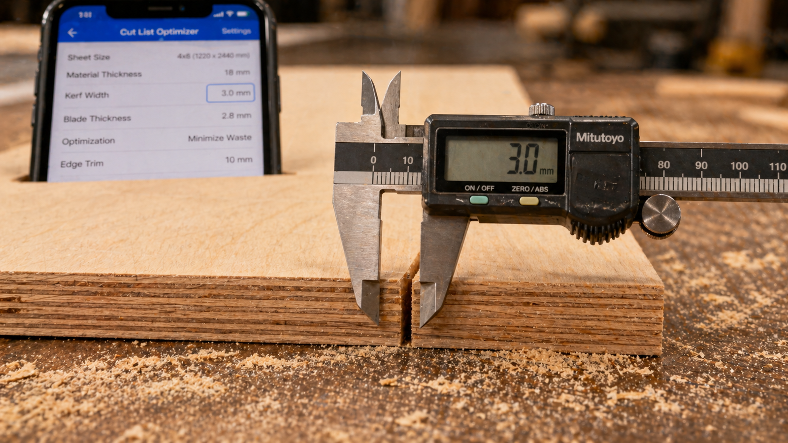
💡 Pro Tip: Don't assume your kerf — measure it. Make a test cut on scrap, then measure the width of the kerf channel with a digital caliper. Blade manufacturers publish nominal kerf widths, but real-world kerf can vary slightly depending on blade sharpness, feed rate, and material density. For precise cut planning, your measured kerf is more reliable than the spec sheet.
How to Calculate Kerf Manually in a Cut List Layout
If you're planning cuts in a spreadsheet or on paper rather than using a cut list app, here's the step-by-step method for manually incorporating kerf into your layout calculations.
Step 1 — Count the Cuts in Each Direction
For each row or column of parts on your sheet, count the number of cuts required to separate them. For a row of three parts side by side, you need two cuts between them (not three). The formula is:
Number of internal cuts = Number of parts in row − 1
Step 2 — Calculate Total Kerf Loss Per Row
Multiply the number of internal cuts by your kerf width:
Total kerf loss = (Parts in row − 1) × Kerf width
Step 3 — Add Trim Allowances
Add your factory edge trim allowance to the total. If you're trimming 10 mm from one reference edge before cutting parts, add 10 mm to the total consumption for that dimension:
Total sheet usage = Sum of part dimensions + Kerf losses + Trim allowances
Step 4 — Verify Against Sheet Size
Check that total sheet usage does not exceed the nominal sheet dimension. If it does, you need to adjust the layout — typically by moving a part to a new sheet or finding a tighter nesting arrangement. This is where manual planning becomes genuinely difficult on layouts with 10+ parts, and where a cut list optimizer proves its value most clearly.
Worked Example: Kerf Calculation on a Cabinet Side Panel Strip
Let's walk through a realistic kerf calculation for a single rip-cut strip. You need four panels, each 300 mm wide, from a 1220 mm wide sheet. Your table saw uses a standard 3 mm kerf blade, and you'll trim 8 mm from the factory edge before cutting.
| Element | Calculation | Total (mm) |
|---|---|---|
| 4 panels at 300 mm wide | 4 × 300 | 1200 mm |
| 3 internal kerf cuts at 3 mm | 3 × 3 | + 9 mm |
| Factory edge trim | 1 × 8 | + 8 mm |
| Total sheet width required | 1200 + 9 + 8 | 1217 mm |
| Sheet width available | Standard sheet | 1220 mm |
| Remaining margin | 1220 − 1217 | 3 mm ✓ Fits |
Without kerf accounting, this layout appears to have 20 mm of margin. With accurate kerf and trim accounting, the true margin is just 3 mm — barely enough. If you'd used a slightly wider trim allowance or a thicker kerf blade, this layout would have failed. This is why precision matters, and why the Cut Optimizer app performs these calculations on every row and column of every sheet in your project simultaneously.
How Kerf Affects Sheet Count on Larger Projects
Kerf doesn't just affect individual part dimensions — it affects how many sheets you need to buy. On a large cabinet project with 40+ parts across multiple sheets, ignoring kerf in your pre-purchase material estimate is one of the most reliable ways to run short mid-project.
Here's a realistic scenario illustrating the sheet-count impact of kerf on a medium-complexity project:
| Planning Method | Parts | Kerf Accounted? | Sheets Estimated | Sheets Actually Needed |
|---|---|---|---|---|
| Manual (no kerf) | 42 parts | No | 5 sheets | 6 sheets ✗ |
| Manual (with kerf) | 42 parts | Partial | 6 sheets | 6 sheets ~ Close |
| Cut list optimizer app | 42 parts | Full (every cut) | 5 sheets | 5 sheets ✓ |
The optimizer achieves a lower sheet count while fully accounting for kerf because it simultaneously optimizes part arrangement. Manual planning that correctly accounts for kerf but uses an inefficient arrangement often overestimates sheets needed. The Cut Optimizer finds the tightest valid arrangement with kerf built in, giving you the most accurate and economical result.
Kerf and CNC Routing — Special Considerations
CNC routers present a unique kerf challenge. Unlike a saw blade that passes through a sheet in a straight line, a router bit follows a toolpath that can include tabs, lead-in and lead-out moves, and inside corners with radius limitations. The nominal kerf (bit diameter) is larger than most saw blades — typically 6.35 mm for a ¼" bit — and toolpath offsets must account for this in the CAM software.
When using the Cut Optimizer app for CNC nest planning, set your kerf value to your router bit diameter and add a small additional margin for toolpath geometry. A ¼" bit running a full perimeter cut needs a minimum of 6.35 mm between adjacent parts — slightly more in practice to allow for toolpath lead-ins and any material movement during cutting. Most CNC woodworkers use 7–8 mm between parts as a safe kerf+margin value for ¼" bits.
💡 CNC Tip: For CNC nest planning, your "kerf" value in the optimizer should equal your router bit diameter plus any toolpath offset clearance you use in your CAM software. For a ¼" (6.35 mm) bit with a 0.5 mm toolpath offset, enter 7.35 mm as your kerf in the cut list optimizer.
Setting Kerf in the Cut Optimizer App
In the Cut Optimizer app for iPhone and iPad, kerf is set at the project or stock panel level — not per part. This is the correct architecture: kerf is a property of the saw and blade, not the individual parts being cut. Here's how to set it up correctly:
- Open your project and navigate to the stock panel settings
- Enter your kerf value in the kerf field — the app supports both millimetres and fractional inches, so you can enter "3 mm" or "⅛"" depending on your working units
- Run the optimization — every gap between adjacent parts in the generated layout will automatically include the specified kerf width
- Verify in the layout viewer — zoom into adjacent parts on the cutting diagram to confirm the kerf gap is visible and correctly applied
- Check the waste statistics — the waste percentage displayed includes kerf loss, giving you a true picture of material consumption
If you switch to a different saw or blade mid-project — say, moving from a table saw to a track saw for breaking down full sheets — you can update the kerf value and re-run the optimization in seconds. The Cut Optimizer recalculates the entire layout instantly without requiring any changes to your part dimensions.
✅ Verdict: Saw kerf is not a minor rounding error — it's a measurable, cumulative material loss that affects part accuracy, layout validity, and sheet count on every project. The correct approach is never to modify part dimensions for kerf, but to enter a single accurate kerf value into your cutting layout tool and let it propagate correctly through every spacing calculation. A dedicated cut list optimizer app does this automatically, accurately, and in seconds — eliminating the most technically demanding part of manual cut planning.
📱 Stop Guessing Your Kerf — Let Cut Optimizer Calculate It
Enter your blade kerf once and Cut Optimizer handles every spacing calculation across every sheet in your project. Supports table saws, track saws, panel saws, and CNC routers. Available for iPhone and iPad with metric and imperial input.
Frequently Asked Questions
What is the standard kerf width for a table saw?
The most common kerf width for a standard 10-inch table saw with a full-kerf blade is 3.0–3.2 mm (nominally ⅛"). Thin-kerf blades — designed for lower-power saws and less material waste — typically run 2.4–2.6 mm. For accurate cut planning, measure your actual blade kerf on a scrap piece rather than relying on the blade manufacturer's nominal specification. Enter your measured kerf into your cut list optimizer for the most precise layout calculations.
Should I subtract kerf from my part dimensions in the cut list?
No — this is one of the most common kerf mistakes. Your cut list should always record finished part dimensions: the exact size each piece needs to be when it reaches assembly. Kerf is a property of the cutting process and belongs in the layout tool, not the part definition. When you use a cut list calculator app, the kerf setting adjusts the spacing between parts in the layout automatically, without modifying any of your part dimensions.
How much material does kerf waste on a typical plywood project?
On a medium complexity project — say, 25 parts across three sheets, each sheet requiring roughly 12 cuts — a 3 mm kerf consumes approximately 36 mm (about 1.4 inches) of material per sheet, or 108 mm across the three-sheet project. This is material that simply doesn't exist in any part. It's pure consumption. On projects with tightly arranged parts and limited margin, this accumulated kerf is often the difference between a layout that fits and one that requires an additional sheet.
Does kerf matter for CNC routers as well as saws?
Yes, and CNC kerf is actually larger and more complex than saw kerf for most setups. A standard ¼-inch upcut spiral bit removes 6.35 mm per pass — more than double a full-kerf table saw blade. Additionally, CNC toolpaths require lead-in and lead-out clearance beyond the nominal bit diameter. For CNC nesting, use your bit diameter plus toolpath offset as your kerf value in a cut list optimizer. For a ¼" bit, 7–8 mm is a common practical kerf value used in professional CNC cabinet shops.
What happens if I use the wrong kerf value in my cut list optimizer?
Using a kerf value that's too small causes the optimizer to pack parts tighter than is physically achievable — resulting in a layout where adjacent parts, once the blade kerf is applied, overlap or come out undersized. Using a kerf value that's too large wastes material unnecessarily by leaving wider-than-needed gaps between parts. The practical impact depends on how wrong the value is and how tightly packed the layout is. A 1 mm error per cut across a 20-cut sheet introduces 20 mm of cumulative error — enough to shift a final part significantly off target.
Can I use different kerf values for rip cuts and crosscuts?
In practice, the same blade makes both rip cuts and crosscuts on most table saw setups, so the kerf is identical in both directions. However, if you use a dedicated ripping blade for rips and a crosscut blade for crosscuts, and they have different kerfs, you'd ideally use the larger of the two values in your optimizer to stay on the safe side. Most professional woodworkers standardize on a single combination blade for sheet goods breakdown to keep kerf consistent and predictable across all cut directions.